- NDI division TOP
EddyPortableFX - Flaw Detector Designed as an Educational Tool | For Learning ET

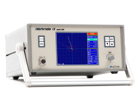
Flaw Detector Designed as an Educational Tool
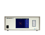
The EddyPortable FX is an eddy current flaw detector designed as an educational tool for learning eddy current testing and for training to prepare for practical examinations for eddy current testing. The detector offers testing views suitable for surface, inner, and encircling probes. Together with an optional probe set and specimens, it helps the user to effectively learn eddy current testing. The detector is compact, easy to carry, and comes standard with a comparator, so it can also be used for testing in non-production lines.
Main Features
- Flaw detection with a surface probe
-
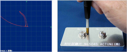
In testing with a surface probe, the detector uses rectangular x and y coordinates to display changes in the impedance of the probe.
Because the detector has a storage (persistence) feature and allows the user to specify the y-to-x ratio of the display and shift the origin in the x or y direction, it can accurately pick up signals from a surface probe which generates large lift-off noises.
- Flaw detection with an inner probe
-
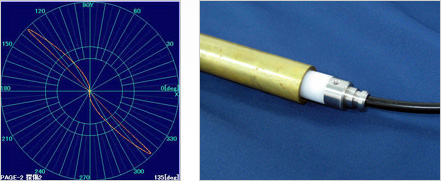
In testing with an inner probe, the detector uses polar coordinates to display changes in the impedance of the probe. In addition, the detector automatically displays the phase angle of a flaw signal in the lower-right corner of the screen, allowing the user to easily create a flaw evaluation curve that represents the relationship between the phase angle and the wall thinning rate of the object being tested. Furthermore, the detector offers a wide range of test frequencies from 1 to 999 kHz, making it also ideal for checking the relationship between the frequency and the depth of penetration. By connecting a two-pen recorder to the x- and y-axis outputs on the detector, the user can directly see the relationship between the vector and time-axis representations of the impedance.
- Flaw detection with an encircling probe
-
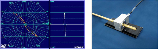
In testing with an encircling probe, the detector shows a vector representation of changes in the impedance of the probe on the left side of the screen, and a time-axis representation of the y-axis (vertical-axis) component of the impedance on the right side of the screen.
Since the user can see vector and time-axis representations of a flaw signal at the same time, their relationship is easy to understand. In addition, the detector displays the amplitude factor of a flaw signal in the lower-right corner of the screen, making it easy to set the sensitivity.
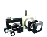
- A handy storage compartment
-
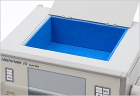
At the top of the detector is a space to store probes, connecting cables, reference specimens, and other equipment. This compartment helps the user to carry, store, and manage materials.
![]()
Download the latest Adobe Acrobat Reader from http://www.adobe.com/.
Specifications
| Probe Type | Self-induction or mutual-induction |
|---|---|
| Method of Excitation | Single frequency testing (6 Vp-p、sine wave) |
| Test Frequency | 1 kHz - 999 kHz (1 kHz steps) |
| Sensitivity | 0.0 dB - 50.0 dB (0.5 dB steps) |
| Phase | 0.0 deg - 359.5 deg(0.5 deg steps) |
| Bridge Balance | Self-holding electonic automatic balance |
| L.P.F. | 10 Hz - 1000 Hz (10 Hz steps) -24 dB/oct |
| H.P.F. | OFF、1 Hz - 100 Hz (1 Hz steps) -24 dB/oct |
| Noise Rejection | OFF or 10 - 50%/FS of maximum amplitude for analog outputs |
| Comparator | 0.20 V - 2.50 V (0.05 V steps) Comparators of x (horizontal axis) and y (vertical axis) are independently adjustable. |
| Display | 6.5 inch TFT color LCD PAGE-1(Surface): Vector representation on rectangular XY coordinates plane. PAGE-2(Inner): Vector representation on polar coordinates plane. PAGE-3(Encircling): Vector representation on polar coordinates plane and amplitude representation on y and time coordinates plane. |
| Screen Sensitivity | 0.5、1.0、2.0 V/div |
| Alarms | (i).Visual red alarm on the display, (ii). Audio alarm |
| Analog Outputs for Recorder | X and Y terminals(BNC connectors): ±10 V/FS, Output impedance is less than 500 Ω. |
| Environmental | Temperature range: 5 ℃ - 40 ℃, Humidity: 10 % - 85 % (without condensation) |
| Dimensions | W: 320 mm H: 149 mm D: 280 mm (not including rubber legs and connecters.) |
| Weight | Approximately 6.5 kg |
| Power | AC 100 V - 240 V 50 / 60 Hz |
| Electric Energy Consumption | Approximately 50 VA |
| Accessory | Power cord (JP plug) |